Following the steps of section 3 "Creating a 3D model" of lesson 1 , we create a test model and name it:
"Multiple Selection - My Name"
At the post of the words "My Name" you will put your name, or a Nickname!
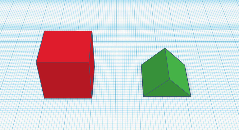
Let's drag any couple of 3D objects onto the work surface .
Now let's try to make a multiple selection .
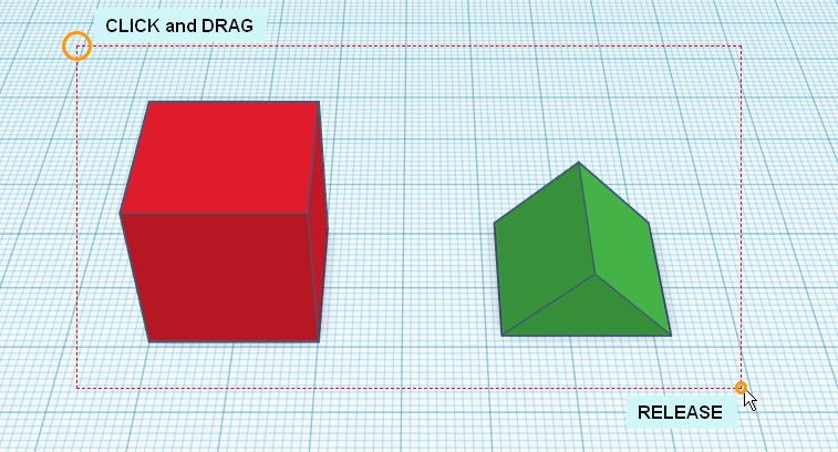
To select multiple objects, simply draw a box with the mouse, which encloses the objects we want to select.
So let's start:
We will see a red dotted box appear .
When we release the mouse button we will have made the multiple selection . We will see that in the properties panel there will be written "Shapes (2)" and therefore 2 selected shapes.
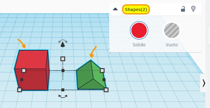
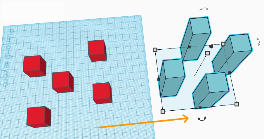
Multiple selection through a box can be performed with any number of objects (see image).
There are some cases in which we cannot perform a multiple selection by drawing a box.
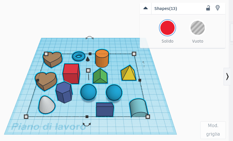
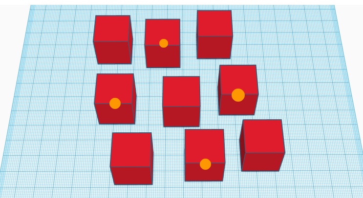
For example, delete all the previous objects, and try to insert 9 cubes on the plane , arranged as in the image.
How can we select only the marked cubes ?
If we draw a box, obviously more cubes will be selected than expected.
The Shift key comes in handy !
To perform a multiple selection, just hold down the Shift key and click, one at a time, on each object we intend to select.
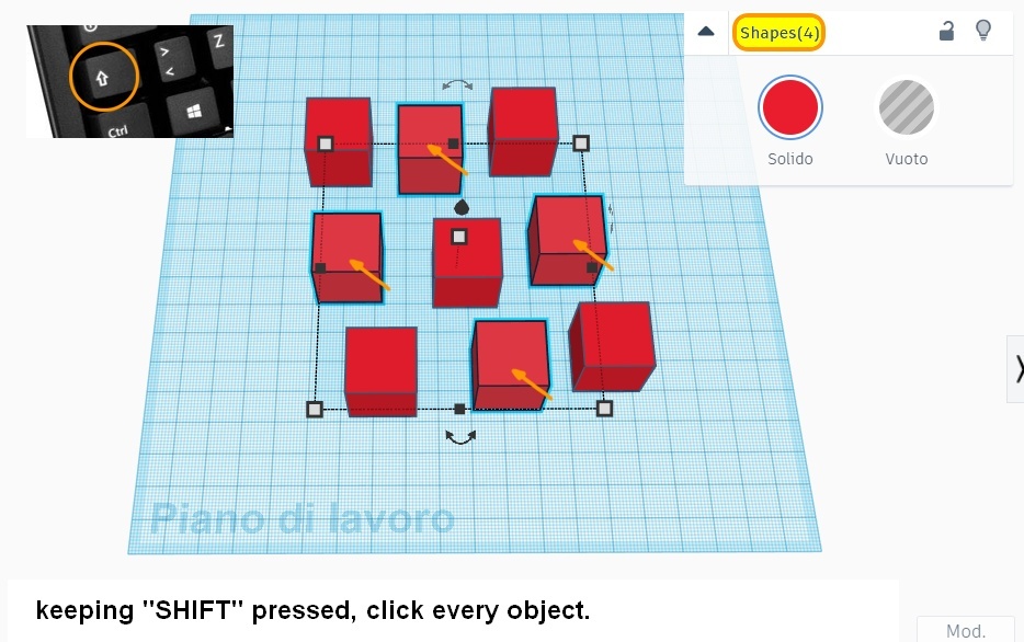
We will see that in the properties panel there will be written "Shapes (4)" and therefore 4 selected shapes.
At the end of the last section 01 "Multiple Selection of Objects" we placed 9 cubes on the plane and selected 4 of them, thanks to the multiple selection performed with the Shift key .
Let's start right where we left off!
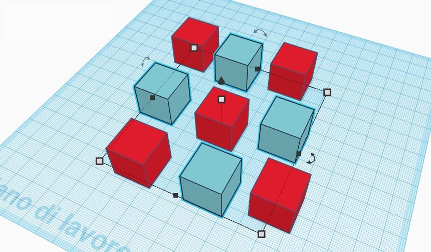
Now that the multiple selection has been carried out, we can act simultaneously on all the selected objects, with the tools learned so far.
For example, pressing the "Solid" button in the "Shape" panel, we open the color palette and choose a new color.
It will be applied to all selected objects.
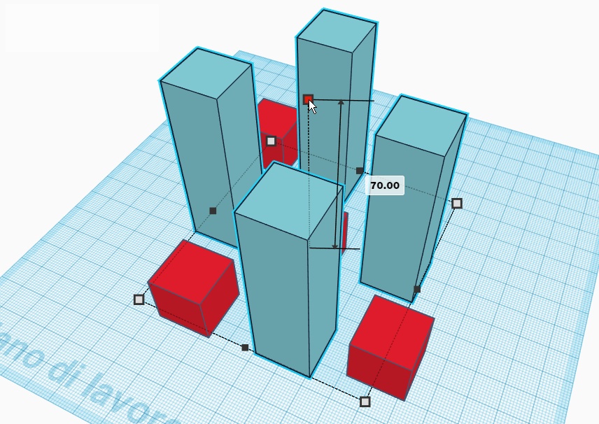
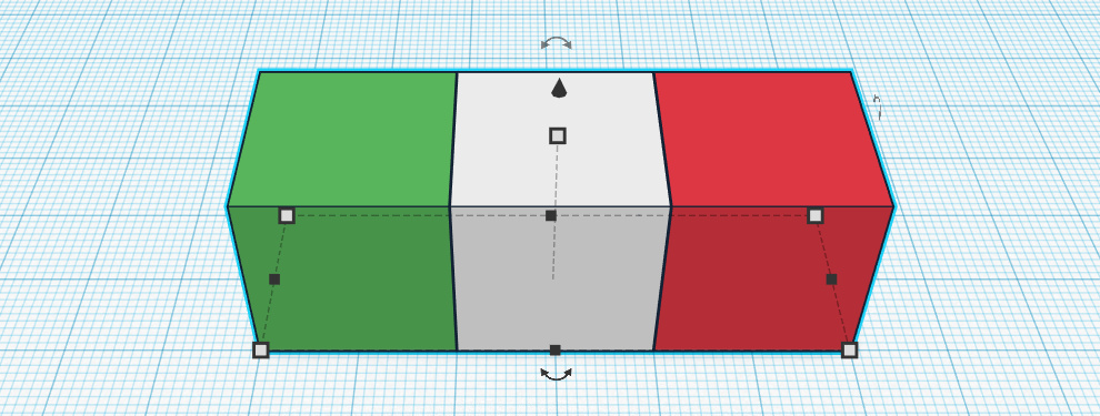
Now that multiple selection has been done, we can also change the shape of all the selected objects.
For example, try changing the height of the objects with the scale tools (in this case the white square at the top of the selection).
The new height will be applied to all selected objects.
Of course we can also move all the selected objects.
By dragging any of the objects on the plane, to move it, we will have the effect of moving all the selected objects.
Following the steps of section 3 "Creating a 3D model" of lesson 1 , we create a test model and name it:
"Merge Objects - My Name"
At the post of the words "My Name" you will put your name, or a Nickname!
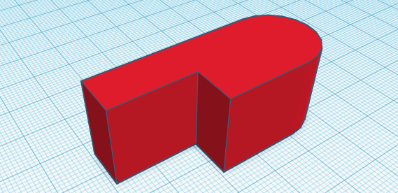
With a couple of cubes and a cylinder, we compose the suggested set of objects (see image)
We will obtain the stylized shape of a whistle.
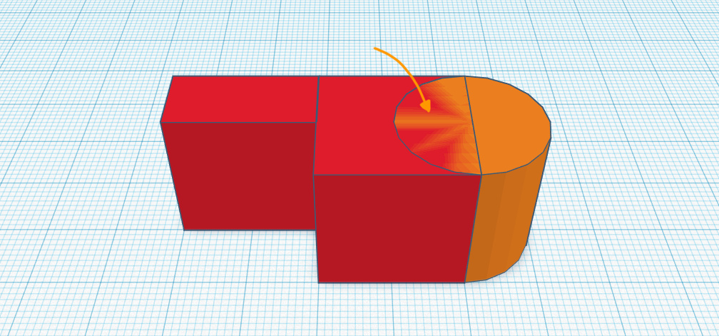
You will notice a " graphic problem " (arrow): it is completely normal : when two objects have exactly the same height, their surface creates strange lines.
Do not worry!
Following the instructions in section 01 "Multiple Selection of Objects", we select all the objects.
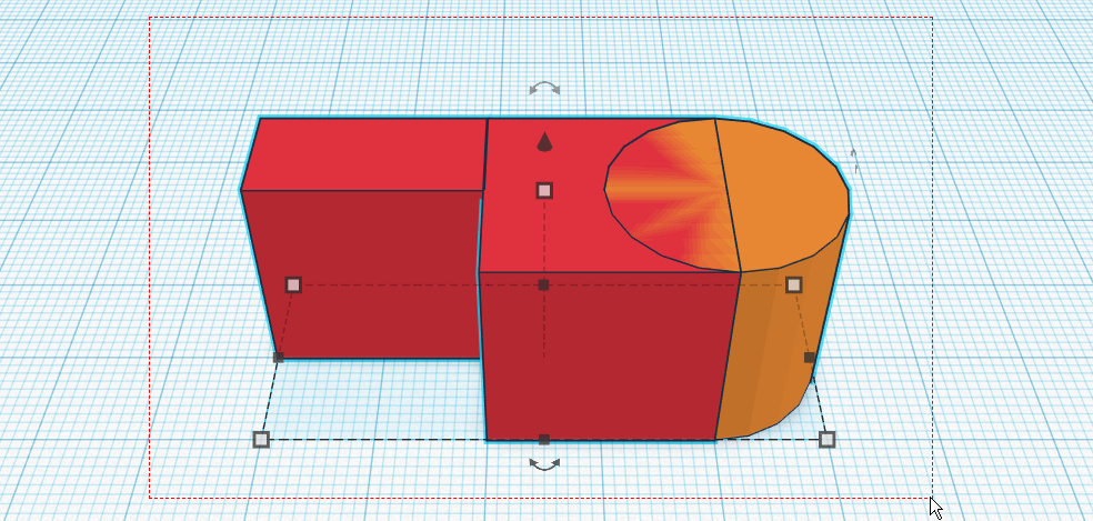
Finally we can merge the selected objects :
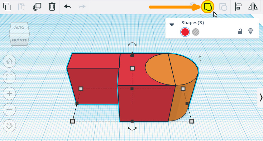
Press the "Group" button [see image] ( the small square joined to the circle ), and you're done.
The keyboard shortcut to merge multiple objects is " CTRL + G "
CAUTION:
Following the steps of section 3 "Creating a 3D model" of lesson 1 , we create a test model and name it:
"Multi-colored objects - My Name"
At the post of the words "My Name" you will put your name, or a Nickname!
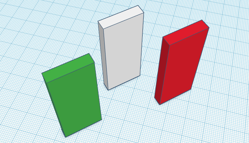
We drag 3 cubes on the work surface and arrange them side by side, as in the figure (see images).
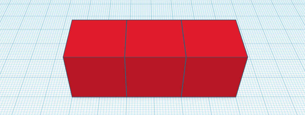
We assign each cube a different color, for example by composing a flag.
It is time to join the objects together. So let's follow the steps for joining more solids:
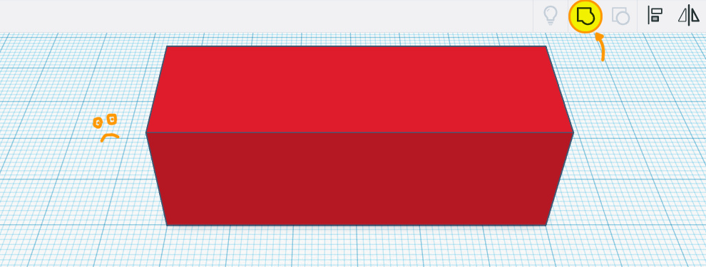
Now we have obtained a SINGLE object (a parallelepiped as wide as the initial group of cubes), evidently of a UNIQUE COLOR .
A composite object can be "colorful", showing in its various parts, the color that the original objects that make it up had.
To achieve this, simply press the "solid" button in the property window, and select the "Multi-color" box under the color palette.
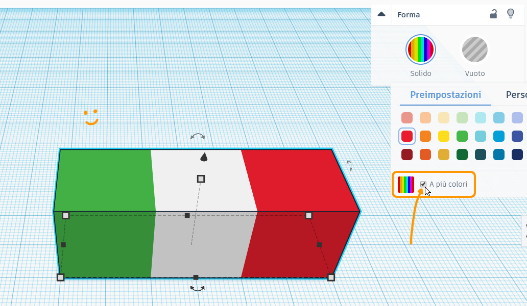
Although the new solid obtained is a SINGLE object , it will now show different colors: the colors of the objects we used to create it.
We still remember that, despite being created by joining multiple objects, the new solid obtained is a SINGLE object , and can be moved, modified, and colored, like any other object that you can find in the column of basic solids.
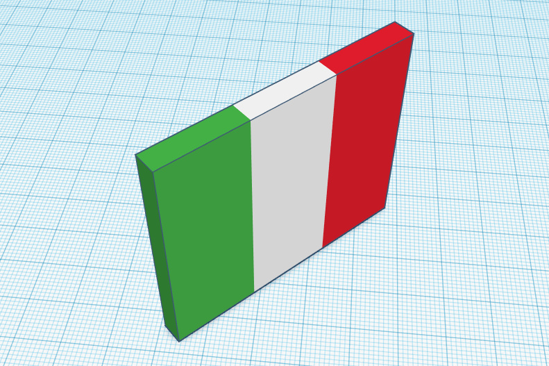
In the previous section we obtained a parallelepiped-shaped object, with the colors of the Italian flag.
Try applying changes !
For example, spread it, press it, rotate it.
It will behave as if the original cubes are perfectly glued together.
Someone has already wondered if it is possible to divide a composite object, to return the original objects that generated it.
The answer is yes, and to divide a composite object simply select it, and then press the "Separate" button [see image], ( the small circle superimposed on the square ).
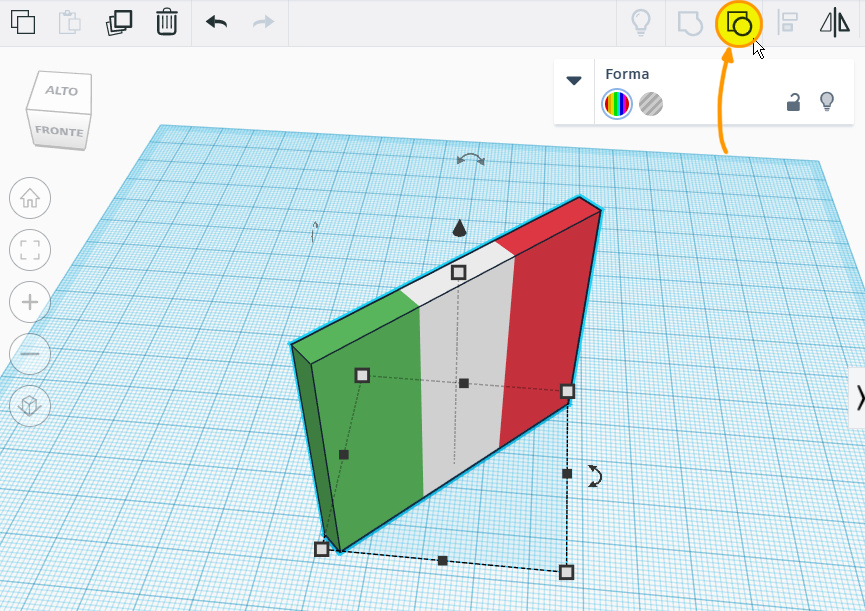
The keyboard shortcut to perform the "Ungroup" action is "CTRL + SHIFT + G"
Try to move the individual objects now: there is no trace of our composite object anymore.
A tip :
If we want to change a color of a multi-colored composite object (because we were wrong or changed our mind, it is enough:
It seems complex, but after a while you will join and separate objects, it will be natural!
Following the steps of section 3 "Creating a 3D model" of lesson 1 , we create a test model and name it:
"Cutting a Tunnel - My Name"
At the post of the words "My Name" you will put your name, or a Nickname!
Let's create a big cube. [see image]
/t1.jpg)
Let's drag another solid onto the work surface, for example a half cylinder .
This will be our cutting object , which will be SUBTRACTED from our initial object.
The cutting operation in Tinkercad can be described as a real subtraction, like when a bricklayer, with the hammer, creates a window in a wall, eliminating many bricks.
We position our cutting object by moving and scaling it so that it traverses our initial cube. [see image]
/t2.jpg)
/t3.jpg)
It's time to apply the "empty" property, which you have certainly wondered about from the very first moments of use of Tinkercad.
We select our sharp object with a click.
We set the "Empty" property by clicking the "Empty" button in the "Shape" property panel.
/t4.jpg)
We are ready for cutting.
To make the cut, a last step is necessary:
We select BOTH the objects involved in the operation, and therefore BOTH the "solid" cube AND the "empty" half-cylinder .
/t5.jpg)
Once this multiple selection has been made, we proceed to press the "Group" button (yes, exactly the same button used for joining solids!)
As you will see, the cube will now present a gallery: the circular roof has been "dug out" of the cube.
/t6.jpg)
Cutting operation - brief: